 ' or
sequences like '&cannot;' then please accept my apologies.
' or
sequences like '&cannot;' then please accept my apologies.
If you occasionally need to design a wound component, but do not deal with the science of magnetic fields on a daily basis, then you may become confused about what the many terms used in the data sheet for the core represent, how they are related and how you can use them to produce a practical inductor.
About your browser: if this character '×' does not look like a
multiplication sign, or you see lots of question marks '?' or symbols
like '' or
sequences like '&cannot;' then please accept my apologies.
See also ...
[↑ Producing wound components]
[ Air coils]
[ Power loss in wound components]
[The force produced by a magnetic field]
[
Faraday's law]
[The
magnetic properties of materials]
[
Unit Systems]
This set of web pages uses the system of units known as the SI (Système International). For more information on the SI, and how it compares with other systems, see Unit Systems in Electromagnetism.
| Quantity name | Quantity symbol | Quantity name | Quantity symbol | |
|---|---|---|---|---|
| coercivity | Hc | core factor | Σl/A | |
| effective area | Ae | effective length | le | |
| effective permeability | μe | flux linkage | λ | |
| induced voltage | u | inductance | L | |
| inductance factor | Al | initial permeability | μi | |
| intensity of magnetization | I | magnetic field strength | H | |
| magnetic flux | Φ | magnetic flux density | B | |
| magnetic mass susceptibility | χρ | magnetic moment | m | |
| magnetic polarization | J | magnetic susceptibility | χ | |
| magnetization | M | magnetomotive force | Fm | |
| permeability | μ | permeability of vacuum | μ0 | |
| relative permeability | μr | reluctance | Rm | |
| remnance | Br |
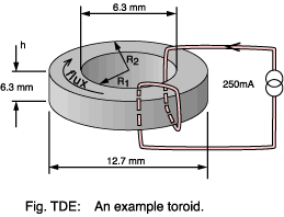 As a concrete example for the calculations throughout this page we consider
the 'recommended' toroid, or ring core, used in this School. Manufacturers use toroids
to derive material characteristics because there is no gap, even a
residual one. Such tests are done using fully wound cores rather than
just the two turns here; but, providing the permeability is high, then the error
will be small.
As a concrete example for the calculations throughout this page we consider
the 'recommended' toroid, or ring core, used in this School. Manufacturers use toroids
to derive material characteristics because there is no gap, even a
residual one. Such tests are done using fully wound cores rather than
just the two turns here; but, providing the permeability is high, then the error
will be small.
| Parameter | Symbol | Value |
|---|---|---|
| Effective magnetic path length | le | 27.6×10⁻³ m |
| Effective core area | Ae | 19.4×10⁻⁶ m2 |
| Relative permeability | μr | 2490 |
| Inductance factor | Al | 2200 nH |
| saturation flux density | Bsat | 360 mT |
Let's take a worked example to find the inductance for the winding shown with just two turns (N=2).
Σl/A = le / Ae = 27.6×10⁻³ / 19.4×10-6 = 1420 m-1
μ = μ0 × μr = 1.257×10-6 × 2490 = 3.13×10⁻³ Hm-1
Rm = (Σl/A) / μ = 1420 / 3.13×10-3 = 4.55×10⁵ A-t Wb-1
[↑ Top of page]
| Quantity name | core factor or geometric core constant |
|---|---|
| Quantity symbol | Σl/A |
| Unit name | per metre |
| Unit symbols | m-1 |
The idea of core factor is, apart from adding to the jargon :-( , to encapsulate in one figure the contribution to core reluctance made by the size and shape of the core. It is usually quoted in the data sheet but it is calculated as -
So for our example toroid we find -
Core factors are often specified in millimetres-1. You should then multiply by 1000 before using them in the formula for reluctance.
[↑ Top of page]
| Quantity name | effective Area |
|---|---|
| Quantity symbol | Ae |
| Unit name | square metre |
| Unit symbols | m2 |
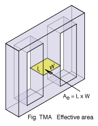 The 'effective area' of a core represents the cross sectional area of
one of its limbs. Usually this corresponds closely to the physical
dimensions of the core but because flux may not be
distributed completely evenly the manufacturer will specify a value for
Ae which reflects this.
The 'effective area' of a core represents the cross sectional area of
one of its limbs. Usually this corresponds closely to the physical
dimensions of the core but because flux may not be
distributed completely evenly the manufacturer will specify a value for
Ae which reflects this.
The need for the core area arises when you want to relate the flux density in the core (limited by the material type) to the total flux it carries -
In the example toroid the area could be determined approximately as the product of the core height and the difference between the major and minor radii -
However, because the flux concentrates where the path length is shorter it is better to use the value stated by the manufacturer - 19.4 mm2. For the simple toroidal shape Ae is calculated (Snelling) as
This assumes square edges to the toroid; real ones are often rounded.
There is a slight twist to the question of area: the manufacturer's value for Ae will give give the correct results when used to compute the core reluctance but it may not be perfect for computing the saturation flux (which depends upon the narrowest part of the core or Amin). In a well designed core Amin won't be very different from Ae, but keep it in mind.
![]() Effective area is usually quoted in millimetres
squared. Many formulae in data books implicitly assume that a numerical
value in mm2 be used. Other books, and these notes, assume
metres squared.
Effective area is usually quoted in millimetres
squared. Many formulae in data books implicitly assume that a numerical
value in mm2 be used. Other books, and these notes, assume
metres squared.
[↑ Top of page]
| Quantity name | effective length |
|---|---|
| Quantity symbol | le |
| Unit name | metre |
| Unit symbols | m |
The 'effective length' of a core is a measure of the distance which flux lines travel in making a complete circuit of it. Usually this corresponds closely to the physical dimensions of the core but because flux has a tendency to concentrate on the inside corners of the path the manufacturer will specify a value for le which reflects this.
In the toroid example the path length could be determined approximately as -
However, because the flux concentrates where the path length is shorter it is better to use the value stated by the manufacturer - 27.6 mm. For a simple toroidal shape le is calculated as
Another common core type, the EE, is shown in Fig: EEE.
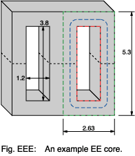 The red line represents the shortest path which a flux line could take
to go round the core. The green line is the longest. Shown in blue is
a path whose length is that of the short path plus four sectors whose
radius is sufficient to take the path mid-way down the limbs.
The red line represents the shortest path which a flux line could take
to go round the core. The green line is the longest. Shown in blue is
a path whose length is that of the short path plus four sectors whose
radius is sufficient to take the path mid-way down the limbs.
This is all a bit approximate; but bear in mind that since manufacturing
tolerances on
permeability are often 25% there isn't
much point in being more exact.
![]() Effective length is usually quoted in millimetres.
Many formulae in data books implicitly assume that a numerical value in mm
be used. Other books, and these notes, assume metres.
Effective length is usually quoted in millimetres.
Many formulae in data books implicitly assume that a numerical value in mm
be used. Other books, and these notes, assume metres.
[↑ Top of page]
| Quantity name | magnetomotive force, alias magnetic potential |
|---|---|
| Quantity symbol | Fm, η or ℑ |
| Unit name | ampere |
| Unit symbol | A |
| Quantity | Unit | Formula |
|---|---|---|
| Magnetomotive force | amperes | Fm = H × le |
| Electromotive force | volts | V = E (Electric field strength) × l (distance) |
MMF can be thought of as the magnetic equivalent of electromotive force. You can calculate it as -
The units of MMF are often stated as ampere turns (A-t) because
of this. In the example toroid core-
Don't confuse magnetomotive force with magnetic field strength (magnetizing
force). As an analogy think of the plates of a capacitor with a
certain electromotive force (EMF) between them. How high the
electric field strength is will depend on the distance between the
plates. Similarly, the magnetic field strength in a transformer core
depends not just on the MMF but also on the distance that the flux must travel round it.
A magnetic field represents stored energy and
where W is the energy in joules. You can also relate MMF to the total
flux going through
part of a magnetic circuit whose reluctance you know.
There is a clear analogy here with an electric circuit and Ohm's Law,
V = I × R.
The analogy with electric potential (voltage) leads to the alternate name
magnetic potential. There is, however, then a risk of confusion
with magnetic vector potential - which has quite different units.
Practical coil windings are made from copper wire which has a current carrying capacity limited mainly by its cross-section. There is therefore a limit to the MMF of a coil in continuous operation of about 3.5×10⁶ ampere-turns per square metre of aperture.
[↑ Top of page]
| Quantity name | magnetic field strength alias magnetic field intensity alias the auxiliary field alias the H-field alias magnetizing force |
|---|---|
| Quantity symbol | H |
| Unit name | ampere per metre |
| Unit symbols | A m-1 |
Whenever current flows it is always accompanied by a magnetic field.
Scientists talk of the field as being due to 'moving electric charges' -
a reasonable description of electrons flowing along a wire.
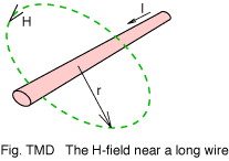 The strength, or intensity, of this field surrounding a straight wire
is given by
The strength, or intensity, of this field surrounding a straight wire
is given by
where r, the distance from the wire, is small in comparison with the length of the wire. The situation for short wires is described by the Biot-Savart equation.
By the way, don't confuse the speed of the charges (such as electrons) with the speed of a signal travelling down the wire they are in. Think of the signal as being the boundary between those electrons that have started to move and those that have yet to get going. The boundary might move close to the speed of light (3x10⁸ m s-1) whilst the electrons themselves drift (on average) something near to 0.1 mm s-1. The electrons would be outpaced by a snail - even if it wasn't in a hurry.
You may object that magnetic fields are also produced by permanent magnets (like compass needles, door catches and fridge note holders) where no current flow is evident. It turns out that even here it is electrons moving in orbit around nuclei or spinning on their own axis which are responsible for the magnetic field.
| Quantity | Unit | Formula |
|---|---|---|
| Magnetic field strength | amperes per metre | H = Fm/le |
| Electric field strength | volts per metre | ε = e/d |
Magnetic field strength is analogous to electric field strength. Where an electric field is set up between two plates separated by a distance, d, and having an electromotive force, e, between them the electric field is given by -
Similarly, magnetic field strength is -
In the example the field
strength is then -
The analogy with electric field strength is mathematical and not physical. An electric field has a clearly defined physical meaning: simply the force exerted on a 'test charge' divided by the amount of charge. Magnetic field strength cannot be measured in the same way because there is no 'magnetic monopole' equivalent to a test charge.
Do not confuse magnetic field strength with flux density, B. This is closely related to field strength but depends also on the material within the field. The strict definition of H is
This formula applies generally, even if the materials within the field
have non-uniform permeability or a permanent magnetic moment. It is rarely used
in coil design because it is usually possible to simplify the
calculation by assuming that within the field the permeability can be
regarded as uniform. With that assumption we say instead that
Flux also emerges from a permanent magnet even when there are no wires
about to impose a field.
A field strength of about 2000 A m-1 is about the limit for cores made from iron powder.
[↑ Top of page]
| Quantity name | magnetic flux |
|---|---|
| Quantity symbol | Φ |
| Unit name | weber |
| Unit symbol | Wb |
| Base units | kg m2 s-2 A-1 |
We talk of magnetism in terms of lines of force or flow or flux. Although the Latin fluxus, means 'flow' the English word is older and unrelated. Flux, then, is a measure of the number of these lines - the total amount of magnetism.
You can calculate flux from the time integral of the voltage V on a winding -
This is one form of Faraday's law. If a constant voltage
is applied for a time T then this boils down to -
How much simpler can the maths get? Because of this relationship flux is sometimes specified as volt seconds.
| Quantity | Unit | Formula |
|---|---|---|
| Magnetic flux | volt second | Φ = V × T |
| Electric charge | amp second (= coulomb) | Q = I × T |
Although as shown above flux corresponds in physical terms most closely to electric charge, you may find it easiest to envisage flux flowing round a core in the way that current flows round a circuit. When a given voltage is applied across a component with a known resistance then a specific current will flow. Similarly, application of a given magnetomotive force across a ferromagnetic component with a known reluctance results in a specific amount of magnetic flux -
There's a clear analogy here with Ohm's Law. You can also calculate
flux as
Flux can also be derived by knowing both the magnetic flux density and the area over which it applies:
A magnetic field represents energy stored within the space occupied
by the field. So
where W is the field energy in joules. Or, equivalently,
[↑ Top of page]
| Quantity name | Magnetic flux density, alias Magnetic induction alias The B-field |
|---|---|
| Quantity symbol | B |
| Unit name | tesla |
| Unit symbol | T |
| Base units | kg s-2 A-1 |
| Quantity | Unit | Formula |
|---|---|---|
| Magnetic flux density | webers per metre2 | B = Φ /Area |
| Electric flux density | coulombs per metre2 | D = C/Area |
Flux density is simply the total flux divided by the cross sectional area of the part through which it flows -
Thus 1 weber per square metre = 1 tesla.
Flux density is related to field strength via the permeability
So for the example core -
Equation TMD suggests that the 'B field' is simply an effect of which
the 'H field' is the cause. Can we visualize any qualitative
distinction between them? Certainly from the point of view of practical
coil design there is rarely a need to go beyond equation TMD. However,
the presence of
magnetized materials modifies formula TMD -
If the B field pattern around a bar magnet is compared with the H field
then the lines of B form continuous loops without beginning or end
whereas the lines of H may either originate or terminate at the
poles of the magnet. A mathematical statement of this general
rule is -
You could argue that B indicates better the strength of a magnetic field
than does the 'magnetic field strength' H! This is one reason why
modern authors tend not to use these names and stick instead with 'B
field' and 'H field'. The definition of B is in terms of its
ability to produce a force F on a wire, length L, carrying current, I, -
where θ is the angle between the wire and the field direction. So it seems that H describes the way magnetism is generated by moving electric charge (which is what a current is), while B is to do with the ability to be detected by moving charges.
In the end, both B and H are just abstractions which the maths can use to model magnetic effects. Looking for more solid explanations isn't easy.
A feel for typical magnitudes of B helps. One metre away in air from a long straight wire carrying one ampere B is exactly 200 nanoteslas. The earth's field has a value of roughly 60 microteslas (but varies from place to place). A largish permanant magnet will give 1 T, iron saturates at about 1.6 T and a super conducting electromagnet might achieve 15 T.
[↑ Top of page]
| Quantity name | flux linkage |
|---|---|
| Quantity symbol | λ |
| Unit name | weber-turn |
| Unit symbol | Wb-t |
| Base units | kg m2 s-2 A-1 |
In an ideal inductor the
flux generated by one of its turns would encircle all the other
other turns. Real coils come close to this ideal when the cross
sectional dimensions of the winding are small compared with its
diameter, or if a high permeability core guides the flux right the way
round. 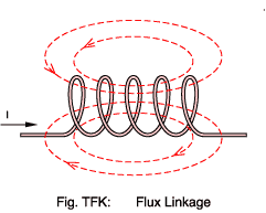 In longer air-core coils the
situation is likely to be nearer to that shown in Fig.TFK: Here we see
that the flux density decreases towards the ends of the coil as some
flux takes a 'short cut' bypassing the outer turns. Let's assume that
the current into the coil is 5 amperes and that each flux line
represents 7 mWb.
In longer air-core coils the
situation is likely to be nearer to that shown in Fig.TFK: Here we see
that the flux density decreases towards the ends of the coil as some
flux takes a 'short cut' bypassing the outer turns. Let's assume that
the current into the coil is 5 amperes and that each flux line
represents 7 mWb.
The central three turns all 'link' four lines of flux: 28 mWb.
The two outer turns link just two lines of flux: 14 mWb.
We can calculate the total 'flux linkage' for the coil as:
The usefulness of this result is that it enables us to calculate the total self inductance of the coil, L:
In general, where an ideal coil is assumed, you see expressions involving N×Φ or N×dΦ/dt. For greater accuracy you substitute λ or dλ/dt.
[↑ Top of page]
| Quantity name | Inductance |
|---|---|
| Quantity symbol | L |
| Unit name | henry |
| Unit symbol | H |
| Base units | kg m2 s-2 A-2 |
| Quantity | Unit | Formula |
|---|---|---|
| Inductance | webers per amp | L = Φ/I |
| Capacitance | coulombs per volt | C = Q/V |
Any length of wire has inductance. Inductance is a measure of a coil's ability to store energy in the form of a magnetic field. It is defined as the rate of change of flux with current -
If the core material's permeability is considered constant then
the relation between flux and current is linear and so:
By Substitution of
Equation TMM and Rowland's
Law -
You can relate inductance directly to the energy represented by the
surrounding magnetic field -
Where W is the field energy in joules.
In practice, where a high permeability core is used, inductance is usually determined from the Al value specified by the manufacturer for the core -
Inductance for the
toroid example is then:
If there is no ferromagnetic core so μr is 1.0 (the coil is 'air cored') then a variety of formulae are available to estimate the inductance. The correct one to use depends upon
Most of these variants are described in early editions of Terman or successor publications. There are too many formulae to reproduce here. You can find them all in Grover.
[↑ Top of page]
| Quantity name | inductance factor |
|---|---|
| Quantity symbol | Al |
| Unit name | nanohenry |
| Unit symbol | nH |
| Base units | kg m2 s-2 A-2 |
Al is usually called the inductance factor, defined
If you know the inductance factor then you can multiply by the square of
the number of turns to find the inductance in nano henries. In our example core Al = 2200,
so the inductance is -
The core manufacturer may directly specify an Al value, but
frequently you must derive it via the reluctance, Rm. The advantage of
this is that only one set of data need be provided to cover a range of
cores having identical dimensions but fabricated using materials having
different permeabilities.
So, for our example toroid core -
The inductance factor may sometimes be expressed as "millihenries per
1000 turns". This is synonymous with nanohenries per turn and takes the
same numerical value.
If you have no data on the core at all then wind ten turns of wire onto it and measure the inductance (in henrys) using an inductance meter. The Al value will be 107 times this reading.
Al values are, like permeability, a non-linear function of flux. The quoted values are usually measured at low (<0.1 mT) flux.
[↑ Top of page]
| Quantity name | reluctance |
|---|---|
| Quantity symbol | Rm or ℜ |
| Unit name | per
henry or ampere-turns per weber |
| Unit symbols | H-1 |
| Base units | A2 s2 kg-1 m-2 |
Reluctance is the ratio of MMF to flux -
In a magnetic circuit this corresponds to
Ohm's Law and resistance in an electric circuit. Compare
Reluctance is also proportional to the core factor, Σl/A, but
inversely proportional to permeability -
Again, compare
where σ is the electrical conductivity of a conductor of given
length and cross-sectional area.
Take care to use the absolute rather than the relative permeability here. So for the toroid example reluctance is then:
A magnetic field represents stored energy and
where W is the energy in joules.
Although it can be a useful concept when analyzing series or parallel combinations of magnetic components reluctance is, like permeability, non-linear and must be used carefully.
[↑ Top of page]
| Quantity name | current |
|---|---|
| Quantity symbol | I, i |
| Unit name | ampere |
| Unit symbol | A |
You might be forgiven for thinking that there would be no need to spell out what current is. That's obvious surely? Your mistake is to forget how hard all writers on electromagnetism strive to obfuscate an already difficult subject. Here's the problem.
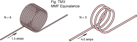 Figure TMX shows two coils with different numbers of turns but
the same
magneto-motive force. When considering the MMF it makes no
difference whether you have twelve turns of wire carrying one amp, or
three turns carrying four amps, or two turns with six amps. As far as
the MMF goes it's all just 'twelve ampere-turns'. You will get just the
same magnetic field in each case.
Figure TMX shows two coils with different numbers of turns but
the same
magneto-motive force. When considering the MMF it makes no
difference whether you have twelve turns of wire carrying one amp, or
three turns carrying four amps, or two turns with six amps. As far as
the MMF goes it's all just 'twelve ampere-turns'. You will get just the
same magnetic field in each case.
Reasoning that detail about the number of turns and the number of amps doesn't matter, only the product of the two, some writers decide to say that the current is twelve amps. They write I = 12 A and leave it to you to decide which scenario brought about that 'current'. This insidious practice carries over to formulae as well.
Which is fine as long as it's consistent and clear to the reader what's happening. If the current changes then, by Faraday's Law we have an induced voltage. You then have to remember that the induced voltage is per turn and not the the total coil voltage. Ambiguity starts to creep in.
It depends, perhaps, on whether you're more interested in physics or engineering. These pages take the latter view and distinguish current from MMF. Current here, then, is what an ammeter reads, and the number of coil turns, N, is written explicitly.
The physicists get their way in the end because, although you might just speak of reluctance as 'ampere-turns per weber', inductance as 'weber-turns per ampere' is getting a little contrived - even if it does reflect the concept of flux linkage rather nicely. But permeability as 'weber-turns per ampere-metre'?
These pages are being converted to use upper case I both for direct current and for a current given as an RMS quantity; whilst the lower case i will stand for instantaneous values of time varying current.
Trivia point: why is the symbol I used for current? Allegedly, it stands for 'electric intensity', as opposed to 'total amount of electricity' (charge). Maxwell, though, used the symbol C for current and used electric intensity to refer to the E-field: what most people today know as electric field strength. So it goes.
[↑ Top of page]
| Quantity name | current density |
|---|---|
| Quantity symbol | J |
| Unit name | amperes per square metre |
| Unit symbol | A m-2 |
Current density is simply the total electric current divided by the area over which it is flowing. Example: if a wire 0.7 millimetres diameter carries a current of 0.5 amperes then the current density is
Or 1.3 amps per millimetre2. A reasonable limit for most
small transformers is 3.5×10⁶ A m-2.
[↑ Top of page]
| Quantity name | Turns |
|---|---|
| Quantity symbol | N |
| Unit name | turn |
| Unit symbol | t |
By tradition, coil calculations use the capital letter N to represent the total number of turns in the coil. Solenoid coils are sometimes described using the lower case letter n to represent the number of turns per unit length. So
Where la is the axial length of the coil.
Naturally, for most designs, the number of turns required is the $64,000 question. The answer comes in a bewildering variety of forms. For the most common case, such as the example toroid core, where the manufacturer has specified Al -
So, if you needed 330 microhenries then
[↑ Top of page]
Flux, field strength, permeability, reluctance ..... it's easy to go into jargon overload. Snelling lists over 360 different symbol uses connected with ferromagnetics. There isn't even agreement about what to call some properties (I say remnance, you say remanence, he says retentivity). You will cope better if you can form a mental picture of the party that these names throw when they get together inside your transformer.
You may find it easier to obtain an intuitive grasp of the relationships between magnetic quantities by thinking in terms of 'magnetic circuits' with flux flowing round a core in a fashion analogous to current flowing round an electric circuit.
| Magnetic quantity | Electric quantity |
|---|---|
| magnetomotive force | electromotive force (voltage) |
| magnetic field strength | electric field strength |
| permeability | conductivity |
| magnetic flux | current |
| magnetic flux density | current density |
| reluctance | resistance |
For example, if you have a transformer with a gapped core then imagine that the core and the gap form a series magnetic circuit with the same flux flowing through both reluctance components in an analogous fashion to a series electric circuit in which the same current flows through two resistors -
compare
There's an entire family of formulae which take similar forms in both the electric and magnetic worlds. Kraus lists most of them.
All analogies break down when pushed too far. This one falls rather quickly if you realise that curent flowing through a resistor dissipates energy while flux flowing through a reluctance does not. In fact you can ask whether flux is a real physical effect at all (in the way that electron flow is).
In transformer design you would normally like to deal in terms of the voltages on the windings. However, the key to understanding what happens in a transformer (or other wound component) is to realise that what the transformer really cares about is the current in the windings; and that everything follows on from that.
The current in a winding produces magneto-motive force -
The magneto-motive force produces magnetic field -
The field produces magnetic flux density -
Summed over the cross-sectional area of the core this equates to a total flux -
The flux produces induced voltage (EMF) -
If you can follow this five step sequence then building a mental image of a magnetic component becomes simpler. Remember, you put in a current and get back an induced voltage. In fact, if you can treat the permeability as being linear, then the constants N, le, μ and Ae can be lumped together into one constant for the winding which is called (surprise!) Inductance, L -
I give the base units for all the quantities in this equation; enabling thrill-seekers to make a dimensional analysis verifying that it is consistent. Right, so then our five step relationship between current and EMF boils down to:
You may be about to complain that you know the EMF on your winding but don't know the current in it. The answer is that the process then works in reverse - the current will build up until the induced voltage is sufficient to oppose the applied voltage. You can find out more by looking at Faraday's law.
How do you take into account the presence of the secondary windings in a transformer? One way is to take the first four steps of the sequence above and apply them separately to each winding (whether primary or secondary). The arithmetic sum over all windings gives total core flux. From the time rate of change of flux you then have the induced voltage in each winding (since you also know the number of turns for each). There are less tedious methods of analyzing transformer operation which you would probably do better using. But they are another story.
[↑ Top of page]
E-mail:
R.Clarke@surrey.ac.uk
Last modified: 2009 May 28th.