|
===Mani Favoriti===
|


====Jaunumi====
Details of pic ICSP and how to use it for pic microcontrollers.PIC ICSP - In Circuit Serial Programming for programming PIC Micros...ICSP gives you a convenient way of programming PIC Micros without removing the chip from the development or production board. All you need is a programmer that provides the ICSP connector (usually a six or four pin molex connector). Click here for more details on how to setup your ICSP system. Click here for a PIC ICSP programmer project schematic.Note: Programmers that are labelled Serial or Parallel both send serial data to the PIC microcontroller through the PIC ICSP circuit. The 'Serial' or 'Parallel' description refers only to the interface used from the PC to the PIC ICSP circuit. Here is the ICSP circuit I use : 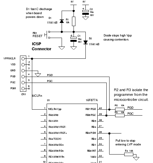 PIC ICSP SignalsICSP provides 6 connections from the pic ICSP programmer to your board as follows :
Note: With the connections made in this order on the connector it will not matter if the connector is placed the wrong way round as GND and VCC are then applied to clock and data. If VCC and GND had been at opposite ends of the connector then there would be a problem. VPP Signal (Signal a programming action)Vpp connects to the reset input of the pic microcontroller labelled MCLR. During programming or verify this signal is raised to the programming voltage (13.5V) - or VCC+3.5V. This signals to the microcontroller that programming/verification is about to start and for older parts, supplies current. Note: Older pic micros used this line to directly power the programming circuit that updates the Flash memory. So this connection had to supply some current. With the newer parts that allow LVP (Low Volt programming) the programming voltage is generated internally so the Vpp signal from the pic ICSP is only used as an indicator i.e. it doesn't have to supply current. VDD/VCC Signal (Power)This connection may supply power to your board - usually using a 5V regulator (probably a 7805). This is ok for some use as you can develop a prototype board without needing any other power supply (just a power brick that plugs into the pic programmer circuit). The only problem with it is that the programmer circuit is not designed for your circuit (does it have a heatsink) and it can also introduce noise to your circuit. If the programmer uses a 78L05 then you will only get 100mA maximum current output. GND SignalThe ground reference - 0V. PGC and PGD Signals (Clock and Data)These are the signals that do the work. Data (PGD) and clock (PGC) transmit data to the pic micro. First data is sent either high or low voltage (0/1). After a suitable time the clock is strobed low to high - rising edge clocking the data into the microcontroller. PGD is also the line driven by the pic micro during verify i.e. it is bi-directional. PGM Signal (Low volt programming signal)The purpose of this pin is to hold PGM low so the microcontroller does not enter LVP mode. It will usually be done using a pull down resistor e.g. 10k. Note: If you program the microcontroller with LVP mode off then this signal will have no effect. Note: PIC microcontrollers ship with LVP enabled - so if you use a brand new chip you can use it in LVP mode. The only way to change the mode is by using a high voltage programmer. What circuit do you need on your target boardNote that the diagram from pic ICSP application note 'DS33023A' specifically goes out of its way to not design it for you saying RB6 and RB7 should be isolated but this depends on your circuit! This is not very helpful so I have included the circuit I use on my development board (See the diagram shown earlier): To ensure you can program and verify correctly two 10k resistors isolate the programmer (and RB6 and RB7) from the rest of the circuit i.e. they stop signals at the other side from interfering with RB6 and RB7 during programming. If you don't use the isolation resistors then loading or driving the pins can stop programming all together. For example if you put an LED on RB6 (PGD) that draws 20mA when on. The output voltage (when the output is on) will be pulled so low that the pic ICSP programmer will not be able to read back the desired voltage i.e. it will give a verification failure. |
||||||||||||